Tuesday, April 28, 2020

Up, Up and Awayyyyy


I do love a big lash-up.  So with that in mind, you do need your multiple locos in that lash-up to all be running pretty much the same speed and respond the same way.  To that end, I need to have a speed matching track.  One of the chaps at the club did one up, thanks Peter A, and at the club we can now match N scale, HO scale and HOn3½ locos with JMRI and the DCC++ system.  It is also handy for running in locos and testing a loco for proper operation.

Since I can't easily get 1200 x 2400 sheets of XPS foam, I got 4 sheets of 30 mm thick XPS foam from Bunnings at 600 x 1200 mm size. With 2 aligned this way and 2 aligned that way, they come out solid as a rock and at the 1200 x 1200 mm size I want.  I used Polyurethane glue that expands slighty, to glue it together. A pile of home made ballast, dirt and rock containers for weight, kept it all down and together for the few hours the glue took to set.


Next I laid down some cork and gave it a quick lick of grey paint to simulate ballast for now and once dry, glued down my dual guage track to cater for my Standard and Narrow gauge HO scale locos.  I just used large pins to hold the track down whilst my glue, 50/50 white glue/water, was dribbled over the track to hold it down sufficiently.


I decided to make a decent job of it and got some 12 x 65 mm and 18 x 65 mm pine timber to protect the edges and she will be good as gold and last me a loooooong time.  The pine does actually have a real purpose - somewhere for the Eye Screws to screw into.  The pine will get a second coat of white paint soon to make it look good as well.  With a 1200 x 1200 mm deck, I can get my HO track at about a 600 mm radius which is well and truely OK for the locos of all sizes.  At some stage soon, I will add an inner ring of cork and whack down some N scale track as well.


Now for somewhere to store it, as it is not small! Quite a while back I was going to only have a very small layout - a 4 x 8 foot one in fact.  To that end, my old man made a great gadget for me.  In the garage, yes my workshop was once a true garage for the car, dear 'ol Dad set it up so I could have a layout.  All you did was back the car out and winch down the layout from the ceiling :-)   The ceiling is very high and this allowed it all to fit, and even jumping I couldn't touch the layout when it was up and away.  So with a step ladder you climbed up and wound the boat winch on the ceiling and it lowered or raised a frame that held the 4 x 8 layout I was building at the time.  Over the years with the layout gone, the winch and frame just sat there out of the way - not now.  


I have made up a spreader frame out of 18 x 65 mm pine and with a pile of Eye Screws, the winch setup via the spreader, attaches (when needed) to the Speed Matching Track and I can drop it down at about the right location to hook up to the computer and do my testing and when not in use it is wound up and sits high up under the ceiling.  I even painted the bottom of the Speed Matching Track  unit, white, so that it blends into the ceiling.


Look, it seems to hover in the air...


So that is what I've been up to for the last 4-5 days now.  So let the speed matching begin.... well, that might be a tad later, but testing of locos is much better on this test rig.


Thursday, April 23, 2020

Rock Island's EMD SW1 Get's Her Lungs


This little 'ol shunter had an NCE DS14SR decoder in her for the first part of her life and then I needed that plug-in decoder elsewhere, so she got a wired in decoder, a TCS T1 for the last few years.  Yes it was messy, but I knew I was going to one day give her a voice, so for a while, she played it down a bit. So now it is time to bring her to full life and voice.


First cab off the rank was to remove the old motherboard and see what I have to play with on the loco side of things.


I had decided that her being a shunter, I wanted smooth operations for slow speed and all those points that would get traversed during a run. So a Stay Alive would be required and I found that I might just be able to squeeze in a home made 4 cell one using some 2.7 volt 1 farad Super Capacitors I have.  So I soldered one up, put some heatshrink over it and placed it up front of the loco. It sort of fitted and I reckoned it'd work.


Welllll, after a bit of more testing I decided that nah, too big.  Not being 100% up to scratch with electronic component workings, I decided to make a 3 cell Stay Alive that would definitely fit. So I placed it into the mix instead.  So all components got layed out.  There is the SoundTraxx TSU-1100 (885001) Sound Decoder, the 11mm x 15mm Sugar Cube Speaker (ESU 50321) and of course the bits to make my 3 cell Stay Alive.


After a lot of moving crap around the place to see what would fit where, I came up with this layout of components as the better of the bunch to work on.


The Stay Alive got my first attention now, as I was alos doing some comparisons of Stay Alives and a 3 cell could now be added to that testing.  The basic components of a Stay Alive are: a Zener Diode to protect the capacitor stack, so in this instance I used a 7.5 volt 1 watt unit
           a Diode (1N4001), which is a 1 watt type, to stop reverse polarity, since we are working with DCC after all
           a 100 ohm ½ watt metal film Resistor to stop inrush current when the Super Caps charge up
           and 3 Super Capacitors of 1 farad and 2.7 volt rating.

So a bit of bending and soldering got the Stay Alive bits into shape for me.


Now you can't just plonk the decoder on top of the motor and flywheel as I think a bit of wear and tear might occur and then sparks might fly. So something to seperate the two was in order. A bit of sheet Styrene was used to make a base for the decoder to sit on and there alread was a couple of holes and scres available from where the old circuit board was mounted.


A bit of mucking around and I found that the Stay Alive would be able to be double sided taped to the roof of the loco shell next to the front headlight. But the sticking of said item would occur later, as testing had to happen first.


So the Decoder was now held down with double sided tape and I moved my attention to the speaker.  It would fit just above the rear bogie gear tower but of course not touching. So a couple of fine flexible wires were soldered onto the little beastie.


The Headlight and Taillight in thei locos are both LED's so I needed to put a current restrictor in place and of course that meant a Resistor. Each power feed to the lights got a 1 k ohm ¼ watt resistor soldered into their power lines and of course heat shrink everywhere to make sure no short circuits happen.


As I worked along I was holding the completed wiring in place with Kapton Tape so as to keep it as tidy as possible so that the lid would go back on relatively easy at the end of this.


Now it was time to test the componets including my home made Stay Alive.  Onto the test track it went and JMRI was fired up.


Yeh, hmmm, riiiiight. All worked well until I fried my little fingers on the Stay Alive - well, the Zener Diode of it anyway. All the sounds worked, so that meant the speaker was OK, the lights worked, even the Stay Alive worked, buttttt.  The big problem was in my only basic understanding of how the Stay Alive is made up.  Theory was all OK, but I hadn't worked into the equation that the Zener Diode needed to dissipate 6 or so volts of power since the 3 caps only came up to 7.5 volts or so.  Hot my friends, very hot.  So it was back to the drawing board on that side of things. I needed to think about it for a while, so I got back to the Speaker.

Since I was going to mount it above the gear tower, I needed to make a small mount to keep the two apart.  Out with the sheet Styrene again and a little glue and a small bracket was made for the speaker to sit on. In the pic it's the white thing under the loco's steering wheel...


Next the speaker was test fitted in the braket and into the loco - all was good.


Then a paint job of matt black acrylic Tamiya Paint over it all so that it is not easily visible in the loco's Cab, and then glued into place with a spot of super glue.


Hmmm, now back to the Stay Alive.  Since a 3 cell version wasn't an option, and a home made 4 cell wasn't going to easily fit because the super caps I have a a tad too big, even with a hammer, I dug out a 4 cell unit I had from LaisDCC.  These are made up of 1 farad 2.7 volt super capacitor cells as well, but their size is a tad smaller and hence actually fitted.


So a bit of double sided tape was used to locate the Stay Alive up under the roof and all wired were captured and held down and told to stay put "or else".


Of course it was all put through full testing under JMRI as well as a test run off the track to prove the Stay Alive to myself.


And here are two videos for you.  The first shows that I will get about 60 cm of track run when power is cut - should cure any points issues I have :-) and the other is the way the loco goes to bed - it's like a kid and stays noisy even when the door closes !


https://youtu.be/TX7kFTwsqpg


Wednesday, April 8, 2020

Adding Sound to a Bachmann 0-6-0 Porter Side Tank


So, for the last umpteen days I’ve been slowly installing a sound decoder into my little HO scale steam loco.  In between, I’ve been building and also testing some Stay Alives and testing some commercial ones as well.  A comparison will come another day, but for today here is the installation for my little side tank mining loco.

The loco is a Bachmann HO scale 0-6-0 Porter Side Tank, Midwest Quarry and Mining #12, that came with a Bachmann decoder already installed.  It was on special a few years back and cute – so I bought one.  It can be used on a small mine or with a repaint – a logging line.  Because of the small space available to me, I decided on the latest SoundTraxx Tsunami 2, model TSU-1100,  Steam-2 sound decoder (part number 884006).  I also used an ESU LokSound 50321 Sugar Cube speaker with an 11mm x 15mm sound box. Since it is only a small loco and has a very modern tiny motor, I decided a 4 cell Stay Alive would work and make sure the loco wouldn’t stall on points and such.  I have a few on hand, but decided to give the LaisDCC Stay Alive a go (part number 860009).  So here are a few spec’s to start with.

The SoundTraxx Tsunami 2 decoder is 27mm x 10½mm x 5mm in size and capable of 1 amp motor stall current.  It has a crap load of sounds built in and all sorts of wonderful features that will take me ages to play with.  It just squeezed into one of the side tanks.   I will have to play for a week or more testing the various loco engine sounds, bell sounds and such and program/select what I want.  I few settings I know won’t be needed from the get go – the loco is definitely NOT a Heavy Loco or an Articulated one – so those sounds won't be needed.


The Stay Alive I got from LaisDCC in China and is made up of 4 cells, each being a 2.7 volt supercapacitor of 1 farad capacitance.  Its size is 26mm x 11.4mm x 8.8mm. It was relatively cheap compared to the big named brands and so far, fingers crossed, it seems to do the job.


The speaker is an ESU LokSound 11mm x 15mm Sugar Cube and I used the 2mm baffle supplied with it to make the boom box for it.  So the baffle bits were the top left, bottom left and of course the speaker.  I glued them together with ZAP brand “Plasti-Zap” Medium CA.  This seems to work nicely with most plastics.  I then soldered on some very fine wire to the speaker.  It was the same stuff that ESU sell but I got it from LaisDCC some time back – nice and fine and flexible and in all the colours you need for DCC wiring.


Now down to it – I took my time.  Yes, I know you say I don’t and you would normally be correct, well this time I did as I didn’t want to bugger this one up like some I’ve done. I so hate having to revisit and fix something I have stuffed up - maybe that's why my new clothesline is yet to be installed....  So the work was spaced over 3-4 days in fact, with testing at each and every step.  First of course was to give it a bit of running in, using the already installed basic Bachmann decoder.  Worked nicely and if it wasn’t for the want of sound, it could have stayed in the loco.

After the run in, I stripped her down – always fun when you have no diagram to follow.  But I got her down into the Boiler, the Cab, and the Mech.  Next I ripped out the Bachmann decoder so I could put in the sound decoder.  The circuit board had to go as well as it was too awkward to modify.  Here is the original board and decoder:


So instead of that original board, I found a very old piece of veroboard kicking around in my old electronics parts boxes, and cut into a rough shape to match the said removed circuit board.  This then sufficed for me to mount the resistors and terminate all the wiring.  Also it allowed me somewhere to glue a surface mounted LED for the front headlight.  It might look ugly, but it is solid, fits and works.


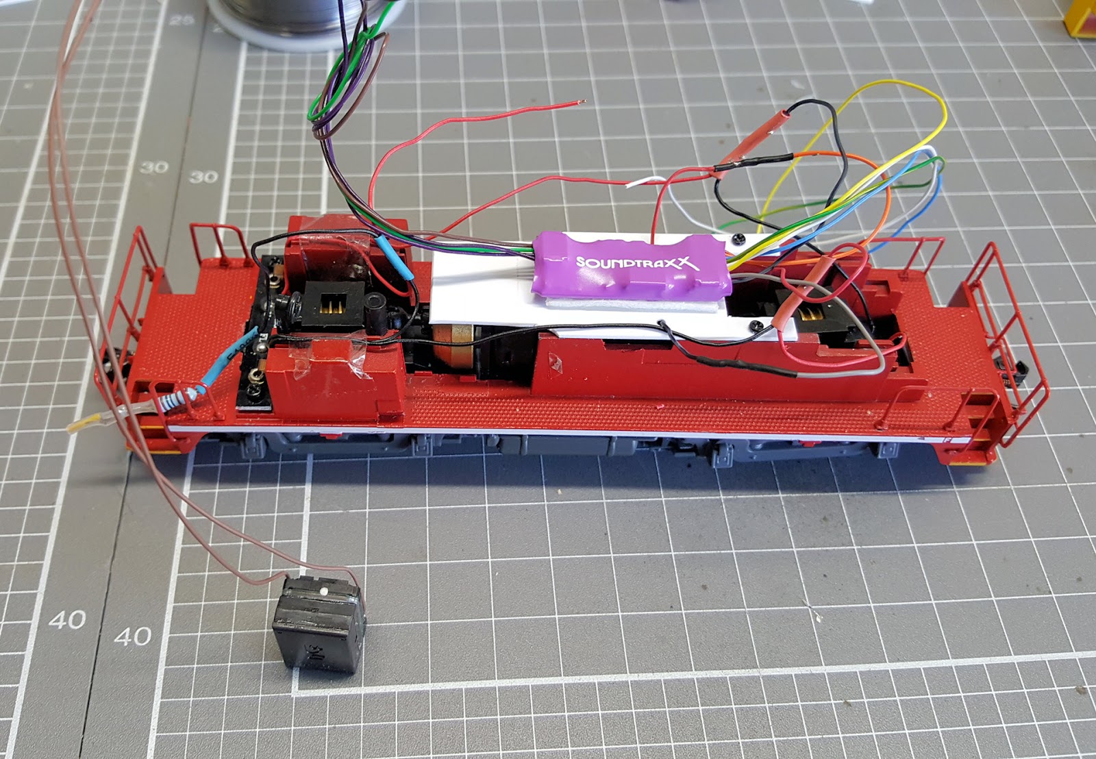
In the photo above, you can see that the loco has the smallest motor for a HO loco I have ever seen.  Yes, that silver thing to the left of the blue and yellow wires is the motor – tiny it is and hence draws bugger all current – runs on the whiff of an oily rag flat battery!  

As I said earlier, each step was tested.  For example, when I soldered in the resistor for the LED, I tested it, then the LED was glued in and tested etc.  This was so that I could pick up a stuff-up then and there and not get to the end and go “oh you piece of ….”   Luckily the garage shields the noise of me swearing from the neighbours!

So then the decoder got temporarily wired in for testing purposes to make sure I hadn’t buggered up anything.


Anyway, then I glued the decoder into the loco in one of the side tanks.  It was a tight squeeze and a few thou had to be taken off the decoder wrapping in the process, but it did fit.  I just can’t believe how many times you have to put the shell on, take it off, measure that, adjust this, do it again, do it again, do it again…  But that’s the way it is, isn’t it J  While I was at it I tested a few of the Stay Alives I had kicking around to see how they went – A M A Z I N G !  20-30 seconds!  Happy chappie here. 


It was then placed on my test track and JMRI fired up and testing performed.  Once I was happy, I could progress further.


The next job was to fit a Stay Alive.  As mentioned earlier, I decided to use the LaisDCC 4 cell unit as I reckoned I could get it in the cab along one side and not visible from the outside.  It had to lose its heat shrink cover in the process though.  Again the Dremel was out and about and few thou here and a few thou there were removed from loco and Stay Alive.  But in the end I was able to get the Cab to go into place properly.

Here we see the temporary fit into the Cab to see the size of it all.  Good, so now I can move forward.


Next I got the Stay Alive and positioned it carefully on the loco base and got out some Thick ZAP CA to hold the Stay Alive down.  Because the Thick variety of CA takes 30 or more seconds to set, I used a lacky band to hold it steady while I went to wet the whistle – my whistle.


The usual temporary wiring was then done so I could test it all again and make sure I hadn’t broken anything. 


Tested OK, so wires were shortened and tucked in and it was time to squeeze the main loco shell on.  It fitted... Just.


Now the speaker had to be put in. I found through measuring and trial and error, that I could get it to sit on the floor along the side of the cab if I got the Dremel tool to part of the coal bunker.  Not really visible, so I proceeded.  Anyway a bit of coal will be added on top of the bunker and you’ll never know.

Again the ZAP Thick CA was used to hold down the speaker.  Wires were then trimmed and soldered on and all was neat and tidy.


Except, from the outside, you could sort of make out the bits.  So some matt black Tamiya paint was brushed on and voila – no can see from the outside.


The cab was then fitted and the job pretty much complete.  It was of course tested and runs nicely.  As a matter of fact, when the loco is bolting along at 50% throttle and the lights are on and the bell belting away and the chuff chuffing away, when you pick it up off the tracks you get about 25 seconds of action and sound before she stops. Dirty points and track can eat my shorts, as Bart used to say.

Here is the little girl in action:  https://youtu.be/3GlfU6L4Ppc