
This little 'ol shunter had an NCE DS14SR decoder in her for the first part of her life and then I needed that plug-in decoder elsewhere, so she got a wired in decoder, a TCS T1 for the last few years. Yes it was messy, but I knew I was going to one day give her a voice, so for a while, she played it down a bit. So now it is time to bring her to full life and voice.

First cab off the rank was to remove the old motherboard and see what I have to play with on the loco side of things.

I had decided that her being a shunter, I wanted smooth operations for slow speed and all those points that would get traversed during a run. So a Stay Alive would be required and I found that I might just be able to squeeze in a home made 4 cell one using some 2.7 volt 1 farad Super Capacitors I have. So I soldered one up, put some heatshrink over it and placed it up front of the loco. It sort of fitted and I reckoned it'd work.

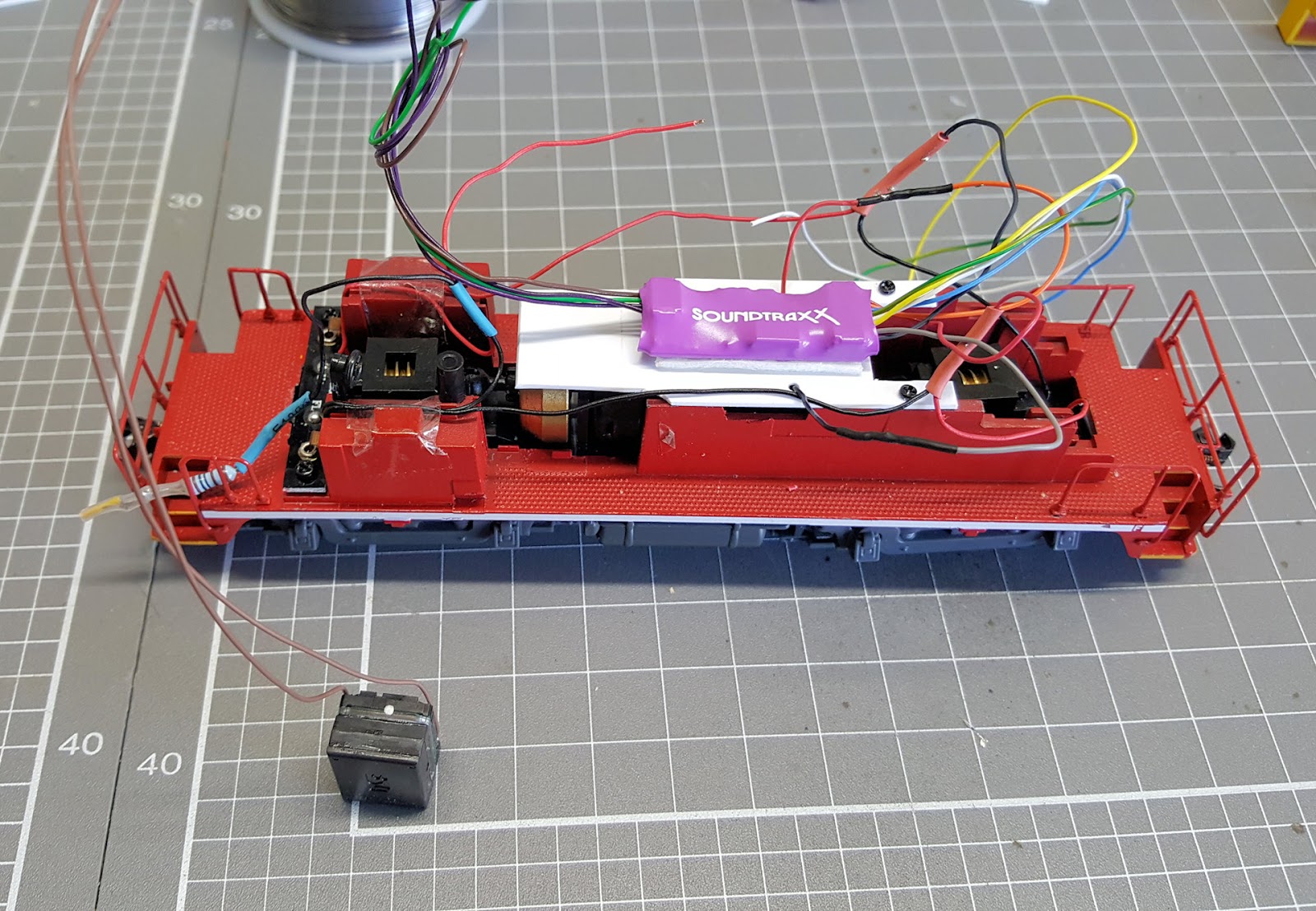
Welllll, after a bit of more testing I decided that nah, too big. Not being 100% up to scratch with electronic component workings, I decided to make a 3 cell Stay Alive that would definitely fit. So I placed it into the mix instead. So all components got layed out. There is the SoundTraxx TSU-1100 (885001) Sound Decoder, the 11mm x 15mm Sugar Cube Speaker (ESU 50321) and of course the bits to make my 3 cell Stay Alive.

After a lot of moving crap around the place to see what would fit where, I came up with this layout of components as the better of the bunch to work on.

The Stay Alive got my first attention now, as I was alos doing some comparisons of Stay Alives and a 3 cell could now be added to that testing. The basic components of a Stay Alive are: a Zener Diode to protect the capacitor stack, so in this instance I used a 7.5 volt 1 watt unit
a Diode (1N4001), which is a 1 watt type, to stop reverse polarity, since we are working with DCC after all
a 100 ohm ½ watt metal film Resistor to stop inrush current when the Super Caps charge up
and 3 Super Capacitors of 1 farad and 2.7 volt rating.
So a bit of bending and soldering got the Stay Alive bits into shape for me.

Now you can't just plonk the decoder on top of the motor and flywheel as I think a bit of wear and tear might occur and then sparks might fly. So something to seperate the two was in order. A bit of sheet Styrene was used to make a base for the decoder to sit on and there alread was a couple of holes and scres available from where the old circuit board was mounted.


A bit of mucking around and I found that the Stay Alive would be able to be double sided taped to the roof of the loco shell next to the front headlight. But the sticking of said item would occur later, as testing had to happen first.

So the Decoder was now held down with double sided tape and I moved my attention to the speaker. It would fit just above the rear bogie gear tower but of course not touching. So a couple of fine flexible wires were soldered onto the little beastie.
The Headlight and Taillight in thei locos are both LED's so I needed to put a current restrictor in place and of course that meant a Resistor. Each power feed to the lights got a 1 k ohm ¼ watt resistor soldered into their power lines and of course heat shrink everywhere to make sure no short circuits happen.

As I worked along I was holding the completed wiring in place with Kapton Tape so as to keep it as tidy as possible so that the lid would go back on relatively easy at the end of this.

Now it was time to test the componets including my home made Stay Alive. Onto the test track it went and JMRI was fired up.

Yeh, hmmm, riiiiight. All worked well until I fried my little fingers on the Stay Alive - well, the Zener Diode of it anyway. All the sounds worked, so that meant the speaker was OK, the lights worked, even the Stay Alive worked, buttttt. The big problem was in my only basic understanding of how the Stay Alive is made up. Theory was all OK, but I hadn't worked into the equation that the Zener Diode needed to dissipate 6 or so volts of power since the 3 caps only came up to 7.5 volts or so. Hot my friends, very hot. So it was back to the drawing board on that side of things. I needed to think about it for a while, so I got back to the Speaker.
Since I was going to mount it above the gear tower, I needed to make a small mount to keep the two apart. Out with the sheet Styrene again and a little glue and a small bracket was made for the speaker to sit on. In the pic it's the white thing under the loco's steering wheel...

Next the speaker was test fitted in the braket and into the loco - all was good.

Then a paint job of matt black acrylic Tamiya Paint over it all so that it is not easily visible in the loco's Cab, and then glued into place with a spot of super glue.


Hmmm, now back to the Stay Alive. Since a 3 cell version wasn't an option, and a home made 4 cell wasn't going to easily fit because the super caps I have a a tad too big, even with a hammer, I dug out a 4 cell unit I had from LaisDCC. These are made up of 1 farad 2.7 volt super capacitor cells as well, but their size is a tad smaller and hence actually fitted.

So a bit of double sided tape was used to locate the Stay Alive up under the roof and all wired were captured and held down and told to stay put "or else".

Of course it was all put through full testing under JMRI as well as a test run off the track to prove the Stay Alive to myself.

And here are two videos for you. The first shows that I will get about 60 cm of track run when power is cut - should cure any points issues I have :-) and the other is the way the loco goes to bed - it's like a kid and stays noisy even when the door closes !
https://youtu.be/TX7kFTwsqpg
LOL - I like that last video! That's alot of stay alive power!
ReplyDelete