So one of my mates went and bought a pair of HO scale ExactRail SD45's. He said he was going full hog and would have sound and DCC in them. But he bought the locos as DC and would do the sound and DCC "later". We advised against it... Just get them already kitted out, a bunch of us told him, it's be cheaper and better... but noooo, he bought the DC ones.
Anyway, so eventually decoders became available after a shortage in the market for a few months. So he got the ESU v5 21 pin sound decoders, but had no idea what speakers to get... sheeeesh. But that's our mate Gabs. So I told him to hand them over and I'd fit 'em up, as he has a tendency of taking a loco shell off and then.... "Help... it's not working any more!" is what we hear around the clubrooms from him.
So I got them home and then de-shelled one so I could figure out what speaker to get as the website wasn't too helpful on the matter. I am glad I took the locos off my mate as it was fun and games. As usual the couplers had to come out. The rear one comes out fine, but the front one has to be dissassembled in situ, as there are tight tollerances and no other way to get it out.
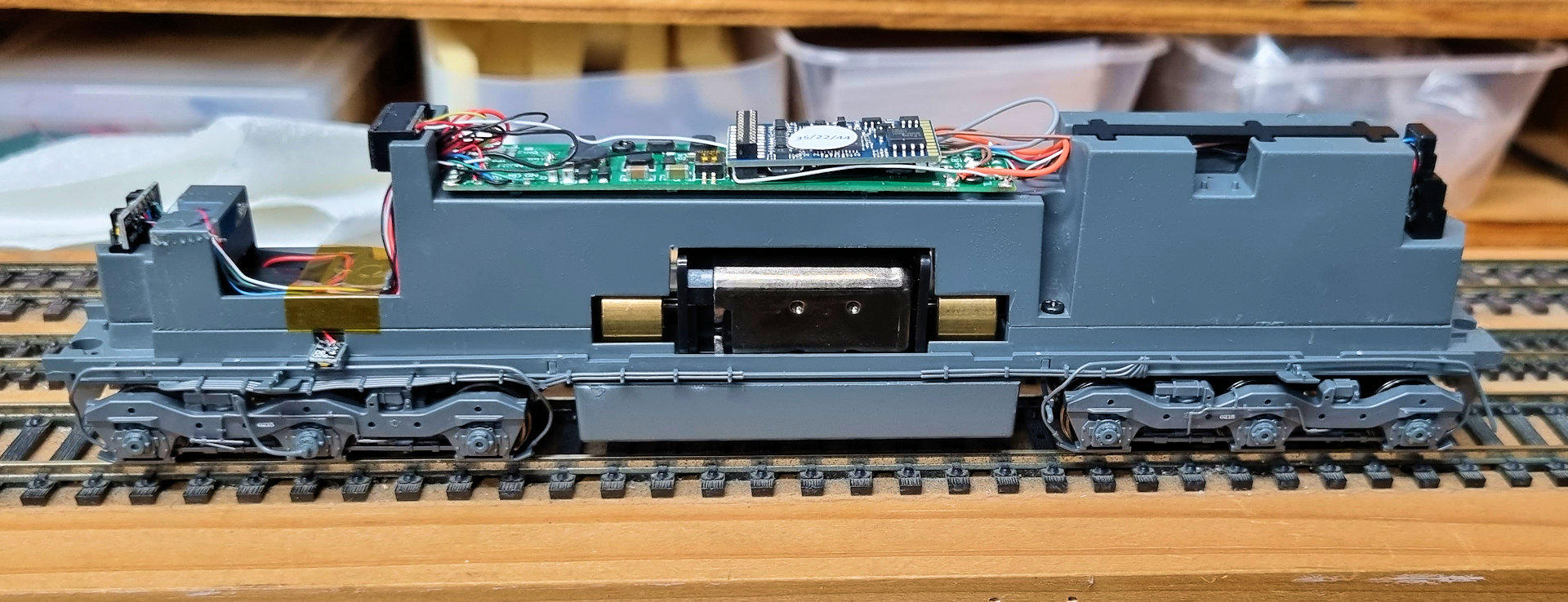
So here we see the loco partially apart. Just putting in a non-sound decoder would have been easy as a small hatch comes off the top of the shell , bottom left, giving access to where the DC board is and where the 21 pin decoder goes in. But to add the sound needs a big pull apart.
So in this shot we can see the 21 pin DC jumper board in place. This comes out easily and the 21 pin DCC decoder will plug in - the easy job.
Now I checked all over the loco mech and chassis and there was no place for speakers - at all. Insert big sad face here. So more dissassembly is required, and there are no instructions with the loco or on the website showing this. Also didn't find anything in YouTube either - "bugger" says I.
So eventually I found two screws on the top side of the loco that allows the chassis to beak apart into an upper and lower part. along this line shown with the trusty tweezers.
But !, I say But ! Some of the wires are going to need to be desoldered from the main board, because there is nowhere near enough slack in the wiring to allow the top and bottom chassis parts to seperate. I can hear that dog in the background go "bugger" again....
By the time I got to the second loco I learned. But it always takes one at first. I thought I'd be smart and "only" take the wires at one end off first.... So on the rear end I took the motor and wheel pickup wires off. This would allow the chassis to swing at the front end and thereby allowing access to the speaker chamber if I was "careful". I still can hear laughter from that smart arse that sits on my shoulder overlooking my work... By careful, you need to be triple careful. I learned and the second loco was easier.
So I succeeded... and above you can see the speaker chamber on the right. All wires at the front of the loco on the left side of the photo are intact... for about 5 seconds... we'll get back to thit shall we.
So four small screws hold the speaker baffle in the chassis, so out they came as did the baffle for use with two sugarcube speakers - the ESU 50321 speaker is the type I use, but there are other brands out there as well that have this size - 11mm x 15mm
But, you say "but didn't you say Gabs didn't have any speakers?". Yep, I did, but I found I had some in my bags of DCC sound decoders and odds and sods of spare parts. Gabs will pay me back after he orders some more for me.
So with a bit of ZAP Plasti-Zap super glue, smeared along the edges of the speakers, I popped them into the baffle.
Next the wires were soldered on. I wired the pair of speakers up in parallel as ESU decoders can handle that and they then sound much better. So 2 x 8 ohm speakers in parallel gives 4 ohms of impedence and ESU decoders handle that juuust fine.
Next the baffle goes back into the chassis and the wires will eventually go up the passage where the boggie pickup wires go as well.
Know how earlier that fellow on my shoulder was laughing, well it was because when I swivelled the chassis halves apart, I snapped off two very fine wires that go to one of the side frame lights that oversee the front bogie - arrggghhhh.
So a LOT of buggerising around to solder them back on was required, including loosening up all the wires near it.
Once soldered in place I was able to tidy up the wires.
Then I held them in place with some Kapton tape.

Then it was the question of where in blue blazes do the speaker wires go?
A quick side note. A surprise :-) The locos come with stay alives! You can just make out the tops of two big capacitors under the main board and drilled into the chassis.
As I said before, there are no instructions, so I shot a hopeful email off to ScaleTrains. I actually got an email from them less than a day later - thanks fellas :-) So the speaker wires do go where I thought - the + and - "S" pads on the main board.
Next the chassis was screwed back in place and the motor wires and bogie pickup wires soldered back into place. The wires, with all the others, were then tidied up in the top of the chassis.
Then the small plastic cable tidy cap snapped back in place to keep the jumpy fellas in place.
I then plugged the ESU decoder into my ESU test rug and connected it up to the PC and fired up the ESU Programmer software. The firmware on the decoder got an upgrade and then I pushed the sound file onto the decoder. ScaleTrains supplies the relevant sound file on their website - nice one fellas :-)
And then the decoder was tested and ready to install later.
The ESU sound decoder went in next - easy peasy.
Then it was onto the test track and see if I got it all correct.
Testing worked, so then it was time to fire up JMRI and do some tweaking for consist running and all tweaks one normally does - including the ESU tweak of CV54. Set it to 0, put the loco on the track and hit F1. The loco takes off down the track for 2 to 3 feet then stops. What it has done is test the motor under load and auto-adjust some motor CV's - don't ask for any more technical answer here - JUST DO IT - makes for much nicer loco running. But this trick is ONLY for ESU decoders.
All tests were good and I then shot Gabs over a list of all 31 functions so he could print himself a copy so as to be able to drive it all.
I was able to find another pair of sugarcubes so was able to do his second loco as well - so on Saturday he can have two running around going ding ding, brmm brmm and rumble rumble.
Time for a cuppa I think - see ya next time.