A fellow QR modeller asked me the other day about fitting a Stay Alive (or Keep Alive - what's in a name) in a Wuiske brand of QR 2100 loco, in HO scale.
So some research with my loco was in order and then eventually I decided to progress and whack a Stay Alive in my QR 2100 loco. My plan is to have all my QR locos with stay alives to cater for dirty track and poor trackwork that you sometimes come across on some layouts... Not that my wheels would EVER be dirty... no, never... ;-)

Step one was to rip the loco's shell off - carefully. Crikey that bench of mine is getting messy again! QR locos are so narrow and not too tall either - not much room I'm afraid. And this loco has two parts of sweet FA space to play with.

I proceeded to see where I could plonk a Stay Alive. It turned out there's no room for a home made one, be it a five or a four cell version. So I got the measurements for the ESU single cell Stay Alive - they call it a PowerPack, from the ESU website via a google search (careful what you search for...) and I proceeded to see if it would fit. Bugger - nothing suitable without cutting or grinding the mech.
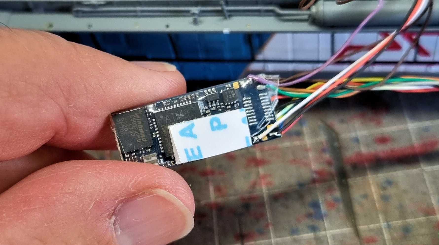
Don't know what made me look, but I did and found that the google search had given me the OLD measurements for the OLD version of the ESU PowerPack. So with the new dimensions now on hand for the ESU 54671 PowerPack I recompared the spaces. Here is the little Stay Alive itself. There is a circuit board that does circuit type stuff with the electricity and there is a single super capacitor soldered to it. It is 15.7 mm x 9.7 mm x 13 mm in size.


I found four possible sites or ways to install the Stay Alive - only one needed any filing or cutting.


In the above shot you can see the Stay Alive on its side and on an angle sitting between the mech tower and the decoder plug area. You just need to make sure it doesn't cover the screw hole that the loco shell uses. Maybe even a piece of sheet styrene to make a plate for it to sit on and keep it from dropping down into the mech.

So I proceeded with installing the Stay Alive in the same area as the decoder. Now as per the photo above, this is the area above the loco I have to play with. The yellow circle marks where I must stay clear to allow the shell screw to come through.


So careful careful when I solder.


Above, she is all screwed together and ready to run.
I think your workbench looks very tidy, and organised - thanks for sharing the picture. I now have some ideas to improve my bench
ReplyDelete